¶ Converting or Replacing the Serial Adapter
¶ Tools required
- Work gloves
- Safety Glasses
- Small flathead screwdriver
- Phillips head screwdriver
- Hex key set (1.5mm - 2.5mm)
- Wire strippers
- Ferrule and ferrule crimping tool (OPTIONAL)
- Tweezers
¶ Synopsis
If you are recieving sporadic 'Lost communication' errors on the 3D Labs HTX, it may be necessary to replace the serial adapter cable. The cable has a logic level converter in-line to facilate translating logic between the mainboard and Raspberry Pi carrier board.
There are 2 sets of instructions. The set you follow will depend on the cable type you have installed. If you have a green CZH Labs breakout board, follow the "new cable version" instructions.
NEW CONNECTOR
If you have a dupont connector block on the Pi GPIO pins, then follow the "old cable version" instructions.
OLD CONNECTOR
¶ Pre-requisites
- Unplug the 3D printer from the wall socket.
- Remove the bottom panel.
- Lay out a shop towel to the left side of the printer to protect your work surface.
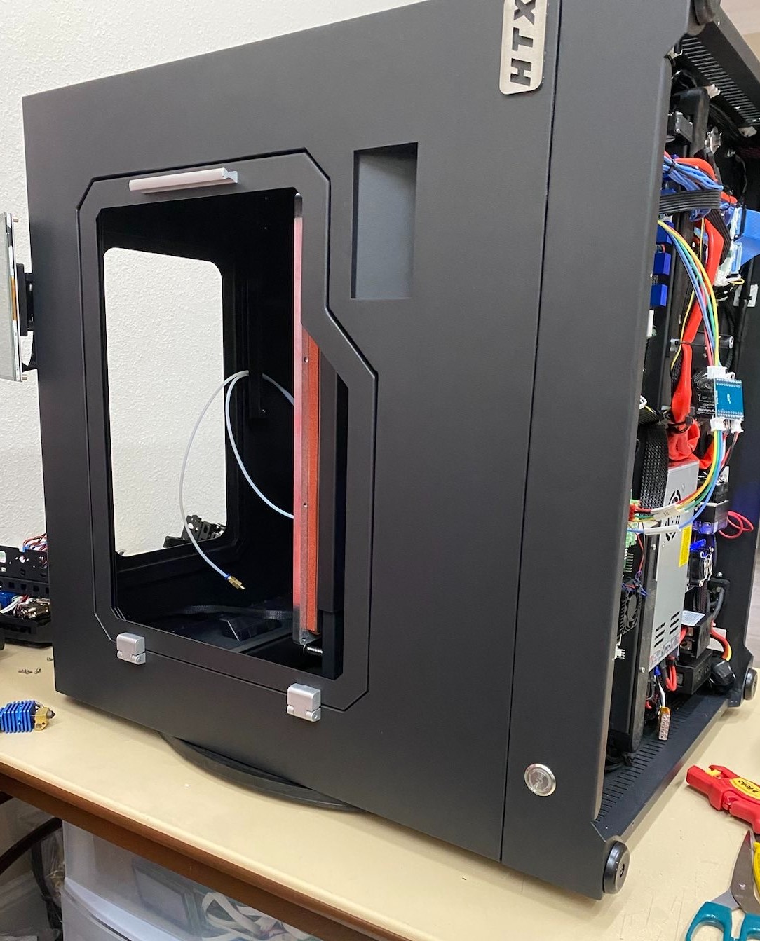
- Two people should lay the printer down as shown:
¶ Instructions (New cable version)
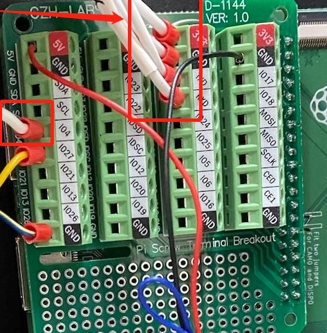
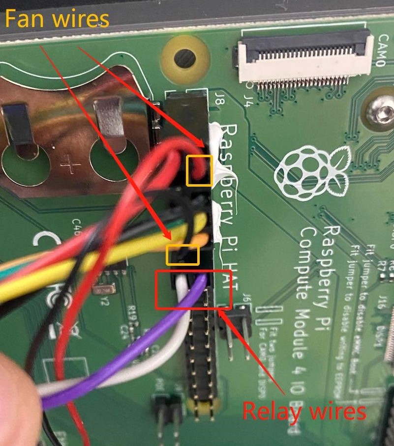
- Disconnect the wires. The breakout board wires can be removed with a small flathead screwdriver
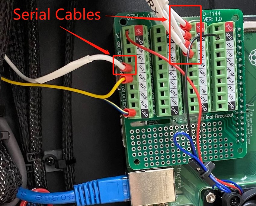
Only disconnect the serial cables shown above. It's not necessary to disconnect the fan or relay wires.

- Disconnect the other end of the cable from the mainboard.
- To install the new cable, reverse the steps above. Use the photo above as reference when installing the new wires.
You may also reference the legend below when reconnecting the wires
| Wire | Breakout board |
|---|---|
| 3V3 (V+) | 3V3 (Any available) |
| GND (V-) | GND (Any available) |
| RST | IO4 |
| RX | RXD |
| TX | TXD |
¶ Instructions (old cable version)
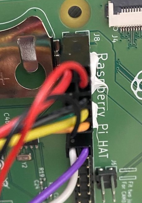
- Unplug the old dupont connector from the GPIO pins on the carrier board.
- Remove the FAN and RELAY cables from the dupont connector with tweezers by lifting up the little tab and pulling the wire out carefully:
- Install the breakout board onto the GPIO pins and brass standoffs.
Note:
You may have to remove the screws holding down the Pi carrier board so you can install the brass standoff in the corner. The breakout only needs one post installed, so just pull the board out enough to get the screw through the underside and install the brass post onto it.
- Install the other end of the connector into the mainboard.
- Zip tie the cables onto neighboring wires gently to secure them.
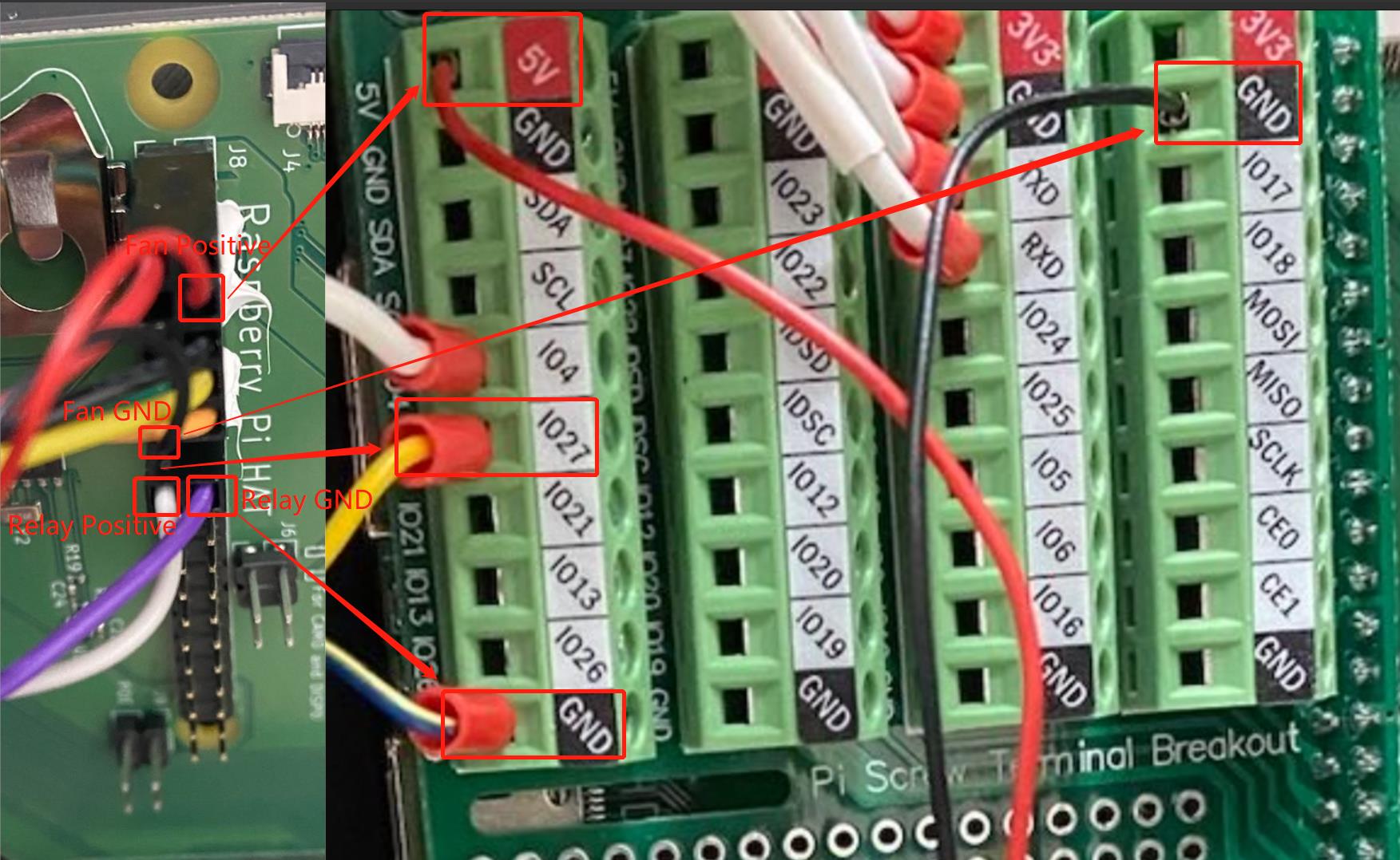
- Either strip and crimp new ferulles onto the fan and relay wires, or trim the ends of the existing dupont crimps so they fit into the breakout terminal. Stripping the wires and twisting is also acceptable for installing into the breakout.
- Use the following image as a reference when plugging the old cables removed in step 2 into the breakout board.
¶ Troubleshooting
- Bed doesn't power on after installing new serial cable:
- You may have the relay cables inverted.
- Try swapping the relay cables in the breakout. You should here a distinct "click" when the printer boots up. This means the relay is being activated and working, and the bed should power on.
- No temperature readouts on the touch screen.
- This means the control board is not communicating with the host.
- Try swapping the RXD and TXD connections on the breakout board to see if that resolves the issue.
- If not, check all wiring for breaks, loose connections, or bad crimps.